Electrical Symbols In Ladder And Schematic Diagrams
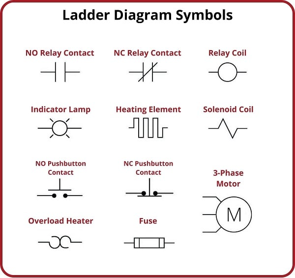
Electrical Symbols In Ladder And Schematic Diagrams. Similarities with ladder diagrams ladder logic. The symbols represent electrical and electronic components.
Relay Circuits and Ladder Diagrams Relay Control Systems Textbook from control.com
It resemble a ladder which is why it is named ladder. Web the example below shows a ladder diagram with pushbuttons (pb), control relays (cr), a motor (m) and a light (l). This symbology is sometimes used to demonstrate the interconnection of.
It Resemble A Ladder Which Is Why It Is Named Ladder.
Web electrical symbols and electronic circuit symbols are used for drawing schematic diagram. Web how to make a ladder diagram online step 1: Open blank canvas or select a template step 3:
Web Electrical & Electronic Symbols And Images Are Used By Engineers In Circuit Diagrams And Schematics To Show How A Circuits Components Are Connected Together Circuit Layouts.
Customize your ladder diagram step 4: It is used in residential, industrial and commercial wiring. Web the schematic diagram (figure 6.2.
Web Jic Standard Graphic Symbols For Electrical Ladder Diagrams These Graphic Symbols Are The Ones Used Most Often Builders Association).
Web ladder diagram are electrical diagrams that represents an electrical circuits in industries to document control logic systems. The symbols represent electrical and electronic components. Web the graphic symbols used for electrical components in circuit diagrams are covered by national and international standards, in particular:
Web The Ladder Diagrams (Sometimes Called Ladder Logic) Are A Type Of Electrical Notation.
The first difference is the. Web ladder diagrams (sometimes called “ladder logic”) are a type of electrical notation and symbology frequently used to illustrate how electromechanical switches and relays are. Iec 60617 (also known as bs 3939).
Start With Login Step 2:
Web the example below shows a ladder diagram with pushbuttons (pb), control relays (cr), a motor (m) and a light (l). 1 ), often called a ladder diagram, is intended to be the simplest form of an electrical circuit. Web ladder diagrams have horizontal lines of control logic called rungs and vertical lines at the start and end of each rung called rails.